Sunday, June 12, 2016

Bringing it all together

User Interface board
Today was the first time I wired everything together.

The major update for today was to use the SX1509 I/O expander with a 3x4 keypad.  Lessons learned included wiring the thing up correctly!  I was stumped for a while when the SX1509 stopped working which turned out to be due to the I2C pins being one pin off on the breadboard.  Close is not good enough!  ;-)

Control and UI boards
I wired up the volume and bandwidth digital pots and added support for updates from the UI board.  Of course I had an issue where my volume updates seem to work but the value was not retained by the control Arduino.  It turns out I needed to use the volatile keyword on a boolean flag used to indicate the end of a data packet (always use volatile for variables that are shared with an interrupt routine!).

I am now able to quickly change bands/modes and use the optical encoder to set the frequency, volume, and rx bandwidth.

So, what's next?
  • Decide how to add 17 meters by using the 80m filter slot.
  • Try the transmitter!
  • Add a tx amplifier  (20 to 40 watts would be nice)
  • Add tx post amp filters
  • Add a T/R relay
Stay tuned!

Saturday, June 11, 2016

A Knob!

Man, a knob really makes a big difference in usability!  I found this aluminum knob on Amazon of all places.

I have been wanting to replace the analog poteniometers with digital pots.  I picked up a few from Sparkfun (Microchip MCP4131).  They are very easy to get working; just throw them on the SPI bus with a chip select and give it 16 bits to set the pot value.  These chips only support 7 bit values (only 127 different values) but that may be good enough (they're definitely good enough to get started).

Since I am now throwing a bunch of chips on the SPI bus, I am running out of pins to use as data and chip selects.  Enter the 74hc595 shift register!  I decided to use two of these to extend my outputs.  One is used as the band and mode selection; the band selection uses the lower three bits (fed into the 3-8 decoder) with two other bits to select the mode (only USB or LSB).  This leaves a few more pins for other modes or other future expansion.   The other '595 is being used as the peripheral chip selects; currently only selecting the digital pots.   The great thing is that I used the built in SPI pins and library to drive the chips -- very cool!

A knob on the UI and digital poteniometers and bus drivers
Now I just have to write code that allows the UI to set the digital pot values -- they are currently hard coded and are set at startup.

Tuesday, May 17, 2016

Rearange

I'm right handed so I rearanged the radio and interface boards around to make it more comfortable to play with.  Now I really need a knob 'cause spinning the encoder shaft is tedious...

No button debouncing was terrible so I whipped up a basic timer comparison test and now band selecting actually works.


Right above the Si5351 board from Adafruit are two potentiometers currently wired to the SSB6.1 labeled as WB/BW and WP/PW on the schematic.  I believe WB/BW is for the receiver band width control and adjusting it does seem to change the audio response.  I think the WP/PW pot controls the mic gain.  Above the two pots are three digital potentiometers I got from SparkFun I want to use instead of the analog pots.  I'd like to be able to use the remote UI to control the radio volume, rx band width, and mic gain and digital pots should do the trick.

Saturday, May 14, 2016

SSB6.1 tranceiver with separate UI

I worked on getting a minimalist user interface working with the microView, a optical encoder, and a single button.  The button cycles through the 6 bands.  I did not add any debouncing code so each button press can result in one or several band changes; it makes selecting the band a bit challenging.  I'll work on integrating the SX1509 I/O expander during the next build.

The minimal user interface is on its own breadboard
The microView interacts with the Arduino pro mini via the TTL serial port.  The band button causes the uView to send commands to set the band and frequency while turning the encoder sends delta frequency commands.  On the display I show the band, the frequency the UI thinks is correct, and the frequency the DDS actually is generating.  So far the 2 controllers seem to keep in sync but I did incorporate a syncing mechanism to make sure they are.

Sunday, May 1, 2016

SSB6.1 RTX with band switching

I made some progress with the SSB6.1 radio.  I wound and added the two 40 meter coils and two of the plastic connectors.  I decided it would be easier to use Female-Male jumpers instead of continuing to tack-solder Male-Male jumpers to the PCB.  It turns out that my tack-soldering was a bit more substantial than I had hoped -- one connection required a lot of solder wick to clean and I manged to lift the PCB foil.  Oops!  Well, stuff happens...  I wired up a small jumper on the bottom of the connector and I'll run it directly to the opto-isolator input pin...

I decided to split the radio control from the user interface.  The radio control will use an Arduino Pro Mini while the user interface can vary as desired.  The connection between the two will be via a TTL serial port possibly using RS-485.  This will allow me to have a sealed RF deck and have a remote user interface.

The SSB6.1 has 6 input pins used to select the band.  I wired up a 74hc295 (a 3 to 8 demultiplexor / decoder) to control the band selection.  This chip has 3 digital inputs (binary 0 to 7) and will assert 1 of 8 outputs.  In this application, this will allow only one band to be active at a time.  Fortunately I had a couple in my parts bin (any guesses as to how long?).  It's been sitting in the package for a while but it still works!

There are 4 other inputs to the SSB6.1.  Two are used to select the sideband and two are used to allow SSB or CW transmit keying.  One is labeled as 'CW' and the other is mysteriously labeled 'DT' (on the schematic, this is the DDSPTT input for SSB keying).  I am currently using a couple of digital output pins on the Arduino to select either upper or lower sideband. It's simple and I have a few pins on the Arduino.

On a whim, I threw some $$ at a kickstarter campaign for a fun speech chip that I may use to provide voice feedback.   There is even a version of the chip with words centered around communications (like phonetics).  It should be interesting to play with.

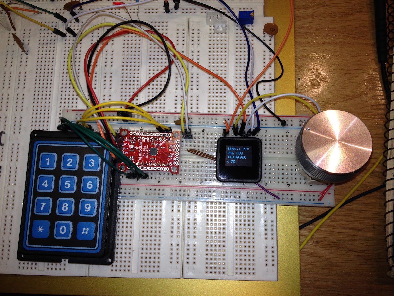
From top left clockwise:  the voice chip, the Arduino Pro Mini with the 74hc295 below it, the SSB6.1, the Si5351 DDS, and finally my trusty old Radio Shack digital logic probe.

With the band and mode selection and a serial connection to the PC in place, I can set the frequency, the band filter, and the mode via keyboard commands.  And, 40 meters sounds great!  :-)


Sunday, April 17, 2016

Old and new parts


I have been building my parts drawer for a few years.  Most of it has come from junque piles at hamfests.  Who can resist looking through boxes of old parts and finding a few gems?  I have built up a stash of keypads of various sizes and types that have been waiting for me to come up with a project.

One issue with the keypads is that you need a way to scan them to recognize the key presses.  Keypads that are wired in a row/column matrix use fewer I/O lines than those that simply close a switch to a common line.  My Grayhill keypads are the latter type; my 16 button keypad has 17 pins -- one for each key and the common pin.  And I have a 20 button keypad that has 21 pins...  I'd like to use a Grayhill keypad with my radio project but 16 pins would tie up all the I/O pins on any reasonably sized microcontroller (not to mention 20 pins).

I like these Grayhill keypads as they allow one to set the label for all keys.  The plastic top of each key pops off and an insert can be placed which will let me to design any layout I want.

I came across the SX1509 I/O expander from SparkFun and ordered a couple.  It provides an I2C interface to 16 I/O pins that can be used in various ways.  Up to 4 devices can be used to provide more I/O pins by setting the I2C address.  Matrix keypads are supported as well as many output options including some cool LED features.

Within a couple of hours of unpacking them, I had a keypad interfaced with the MicroView.

From upper left clockwise:  MicroView, Si5351 DDS, optical encoder, SX1509, Grayhill keypad, SSB6.1
I wired a couple of keys to handle band up and down and updated the firmware to rotate through the DDS frequencies.  Next I have to wire up control lines to the SSB6.1 to actually switch the band pass filters.  Then maybe I'll deal with direct keypad entry of frequencies...

Sunday, March 27, 2016

SSB6.1 with Si5351 RX Working


After a few trials, it looks like I figured out how to get the SSB6.1 to hear stuff.  I had several issues:
  • The board and parts layout diagram had an area for R15-R18 and a part labeled WI (WJ?) but the schematic did not have any reference to these parts.  (Edit:  I discovered that this part is actually M1 -- the letters are transposed on the board so it looks like WI/J.)
  • I was missing the 2 100 Ohm resistors (R42 and R63).
  • C22 is incorrectly labeled as a 2.2uF where a 10uF should be used.
Other than these pretty minor issues, the assembly was straight-forward.  I substituted a couple of non-surface mount resistors for R42 & R63 (they look kinda funny but it will do for now).  The M1 part seems to be for a preamp that actually was included with the parts but I bypassed it since I did not find it on the schematic.  Close examination of a picture of the board from the internet shows a 10pF capacitor installed across 2 pins of M1 instead (the resistors were not populated).

The Si5351 cobbled to the SSB6.1
I decided to only wind the coils for 10m, 15m, and 20m to confirm that I could get something working (and frankly I wanted to get something ready for testing as fast as possible).  I'll wind the 40m coils next.  I am not sure if I'll bother with the 75/80m coils as I'm not sure I will use this radio for that band.  I'd really like to figure out how to get this working on 17m as that is a great band.

The SSB6.1 has an intermediate frequency (IF) of 8 MHz.  During my first tests with the Si5351, I used a DDS mixing frequency of 22 MHz thinking that would give me 14 MHz after the mixer.  Well, it did but I was not able to demodulate signals properly.  The signals all sounded like they were using the wrong side band.  I then tried a DDS frequency of 6 MHz and I started hearing properly demodulated signals!  I then tried a DDS frequency of 13 MHz and was able to hear 15m signals.

After fooling around with the optical encoder code, I am easily able to tune up and down the band.  I display both the DDS frequency and the actual frequency on the microView. I do not have an easy way to switch bands yet; I have to recompile the code and switch jumper connectors.

I read another site about using the Si5351 with a '602 mixer and how the 5351 can overload the '602. I implemented a 10dB attenuator using a few resistors based on information from radio-electronics.com.

Another cool thing about the Si5351 is that I was able to product a sweep frequency to test the receiver incredibly easily.  I simply enabled one of the other clock outputs and it worked great.


Wednesday, March 16, 2016

SSB6.1 RTX

I like portable radios.  I assembled a Wilderness Radio Sierra and an Elecraft K2 and have taken them camping.  They're great for Field Day, too.  But I've been thinking about a backpacking SSB radio that covers several bands that would be fun for day hikes.  Maybe even using it bicycle mobile!

Sometimes you find interesting things on EBay.  I stumbled onto a 6 band transceiver kit (SSB6.1) from a seller in China.  I found it intriguing so I dropped the sixty bucks to have a building adventure.

(Before anyone gets upset about my not buying something from the US:  I also have kits for the R2 and T2 from Kanga US that I am slowly working on.)

This shows the complete contents of the box:  a bunch of surface mount parts, a few NE602s, a few opto-isolators, coil forms, and some connectors.  No instructions, no parts list, no schematic.  Fortunately, the schematic and parts layout are available on the InterWeb.

Soldering surface mount parts can be a challenge but a fine tip iron made that straight-forward.  I was really concerned about winding the coils.  I've wound plenty of toroidal coils but never these.  It turns out (yeah, I said it) that they were pretty easy to wind - I just had to pay attention to what I was doing.

It only has an exciter output level of about 20 mW so I'll need to investigate some amplifier options.

Si5351

Adafruit has a board for the Si5351A.  For 8 bucks you get a itty bity board with 3 clock outputs with a range of 8 KHz to 150 MHz.  I picked up a few to play with homebrew HF radios.  (EtherKit has a version, too.)

I am using the EtherKit library for Arduino.  It is very straight-forward and I was generating clock signals in no time.

This shows the Arduino MicroView handling a rotary encoder and the I2C to the Si5351.