Sunday, June 12, 2016

Bringing it all together

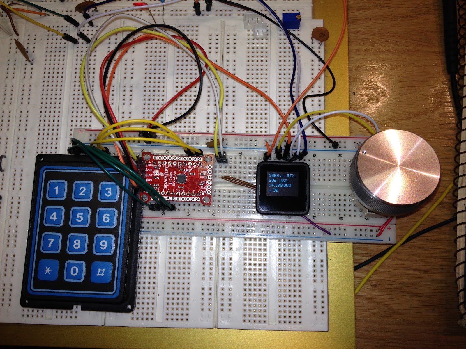
User Interface board
Today was the first time I wired everything together.

The major update for today was to use the SX1509 I/O expander with a 3x4 keypad.  Lessons learned included wiring the thing up correctly!  I was stumped for a while when the SX1509 stopped working which turned out to be due to the I2C pins being one pin off on the breadboard.  Close is not good enough!  ;-)

Control and UI boards
I wired up the volume and bandwidth digital pots and added support for updates from the UI board.  Of course I had an issue where my volume updates seem to work but the value was not retained by the control Arduino.  It turns out I needed to use the volatile keyword on a boolean flag used to indicate the end of a data packet (always use volatile for variables that are shared with an interrupt routine!).

I am now able to quickly change bands/modes and use the optical encoder to set the frequency, volume, and rx bandwidth.

So, what's next?
  • Decide how to add 17 meters by using the 80m filter slot.
  • Try the transmitter!
  • Add a tx amplifier  (20 to 40 watts would be nice)
  • Add tx post amp filters
  • Add a T/R relay
Stay tuned!

Saturday, June 11, 2016

A Knob!

Man, a knob really makes a big difference in usability!  I found this aluminum knob on Amazon of all places.

I have been wanting to replace the analog poteniometers with digital pots.  I picked up a few from Sparkfun (Microchip MCP4131).  They are very easy to get working; just throw them on the SPI bus with a chip select and give it 16 bits to set the pot value.  These chips only support 7 bit values (only 127 different values) but that may be good enough (they're definitely good enough to get started).

Since I am now throwing a bunch of chips on the SPI bus, I am running out of pins to use as data and chip selects.  Enter the 74hc595 shift register!  I decided to use two of these to extend my outputs.  One is used as the band and mode selection; the band selection uses the lower three bits (fed into the 3-8 decoder) with two other bits to select the mode (only USB or LSB).  This leaves a few more pins for other modes or other future expansion.   The other '595 is being used as the peripheral chip selects; currently only selecting the digital pots.   The great thing is that I used the built in SPI pins and library to drive the chips -- very cool!

A knob on the UI and digital poteniometers and bus drivers
Now I just have to write code that allows the UI to set the digital pot values -- they are currently hard coded and are set at startup.