Monday, February 24, 2020

µBITX

I picked up a µBITX transceiver from hfsignals.com (aka Micro Bitx) version 3 to play with.  I thought it would make a good radio for digital modes and maybe use it portable.  There are many web sites describing the radio, so I won't duplicate all of that here.
The neat thing is that the RF section is pre-wired yet it allows for easy modifications.  Since it uses an Arduino and the software is freely available, it is a good platform for playing.  There are many posts on ubitx.net that describe how others are modifying (and fixing) the original design.
The included LCD display is adequate and there are some impressive user mods available but I really want to be able to run it headless. Since I already have an Elecraft K3, I decided to implement a subset of their command set (which is similar to the Kenwood TS-480 commands).

A few mods
Things I did to my µBITX:
Next items:

FT-8
WSPR


Other projects

What time is it?
GPS

I bought a GPS module from adafruit and have been decoding location and time information.  It makes a fun clock when paired with a LED matrix display.  I have to thin down the font to get all the digits to fit...


Halloween fun
Another use for a couple of LED matrix displays...
I call him Morte

Wednesday, August 9, 2017

Lightning Strikes!

We've had an active summer weather-wise.  During one storm, our neighbor's tree was struck by lightning which caused it to split down the middle.  While no other structural damage was done, the resulting EMP did cause a few issues in my house.  Some ports in my network switch failed, my Synology NAS ethernet port failed, and my SSB6.1 kit blew out its receiver (I can still hear loud signals but really faintly).

Fortunately I was able to switch ethernet cabling to unused working ports so I still have Internet access (phew!) and my replacement Synology unit accepted my disks without problems so my network backup is online again.  Thumbs up to Synology -- it recognized that the disks came from another unit and it just worked without fuss.

I decided to get another SSB6.1 kit and start again.  I made a few mistakes with my first build (as described in my other posts) and with the RX amps blown, it seemed like a good time for a clean build.

I just received the kit in the mail and noticed that the board revision is labeled as 'rev: 20170511' which is pretty recent!  The board looks the same so I'm not sure what the updates are.  One difference with this kit is that all the ICs are surface mount whereas my old one had through-hole parts for the SA602 mixers and the opto-isolators.  However, the board layout is still designed for through-hole SA602 chips and it includes adapter boards to mount the surface mount chips to the board.  Hopefully the new kit has all the discrete parts included...

With this build, I am going to make the following changes:
  • have the voltage regulator off the board
  • put the audio amp on another board
  • use components for the 17 meter band instead of 80m
  • be more careful tuning the coils so the slug does not fall off the threads to the bottom...
My case for the radio is a bit thin (about 3 cm) so I am going to move the regulator off the main board.  Mounting it onto the case will give it a decent heat sink.  The audio amp given with the kit (TDA2003) also runs warm so mounting it on the case may be the way to go.  While that chip is pretty hardy and can take a beating (it is used for car radios), it does run a bit warm for my tastes so I may try substituting another amp (cheap LM386?).  Also, having the audio amp off board will make it easier to insert an audio filter before the amplifier.  This one from SotaBeams looks interesting.

Sunday, June 12, 2016

Bringing it all together

User Interface board
Today was the first time I wired everything together.

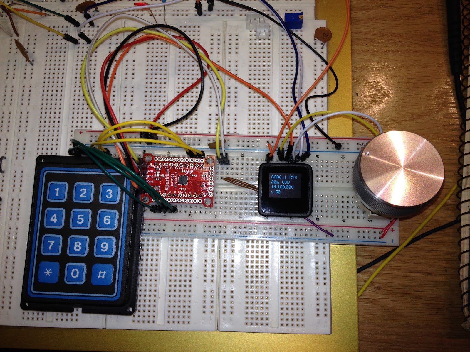
The major update for today was to use the SX1509 I/O expander with a 3x4 keypad.  Lessons learned included wiring the thing up correctly!  I was stumped for a while when the SX1509 stopped working which turned out to be due to the I2C pins being one pin off on the breadboard.  Close is not good enough!  ;-)

Control and UI boards
I wired up the volume and bandwidth digital pots and added support for updates from the UI board.  Of course I had an issue where my volume updates seem to work but the value was not retained by the control Arduino.  It turns out I needed to use the volatile keyword on a boolean flag used to indicate the end of a data packet (always use volatile for variables that are shared with an interrupt routine!).

I am now able to quickly change bands/modes and use the optical encoder to set the frequency, volume, and rx bandwidth.

So, what's next?
  • Decide how to add 17 meters by using the 80m filter slot.
  • Try the transmitter!
  • Add a tx amplifier  (20 to 40 watts would be nice)
  • Add tx post amp filters
  • Add a T/R relay
Stay tuned!

Saturday, June 11, 2016

A Knob!

Man, a knob really makes a big difference in usability!  I found this aluminum knob on Amazon of all places.

I have been wanting to replace the analog poteniometers with digital pots.  I picked up a few from Sparkfun (Microchip MCP4131).  They are very easy to get working; just throw them on the SPI bus with a chip select and give it 16 bits to set the pot value.  These chips only support 7 bit values (only 127 different values) but that may be good enough (they're definitely good enough to get started).

Since I am now throwing a bunch of chips on the SPI bus, I am running out of pins to use as data and chip selects.  Enter the 74hc595 shift register!  I decided to use two of these to extend my outputs.  One is used as the band and mode selection; the band selection uses the lower three bits (fed into the 3-8 decoder) with two other bits to select the mode (only USB or LSB).  This leaves a few more pins for other modes or other future expansion.   The other '595 is being used as the peripheral chip selects; currently only selecting the digital pots.   The great thing is that I used the built in SPI pins and library to drive the chips -- very cool!

A knob on the UI and digital poteniometers and bus drivers
Now I just have to write code that allows the UI to set the digital pot values -- they are currently hard coded and are set at startup.

Tuesday, May 17, 2016

Rearange

I'm right handed so I rearanged the radio and interface boards around to make it more comfortable to play with.  Now I really need a knob 'cause spinning the encoder shaft is tedious...

No button debouncing was terrible so I whipped up a basic timer comparison test and now band selecting actually works.


Right above the Si5351 board from Adafruit are two potentiometers currently wired to the SSB6.1 labeled as WB/BW and WP/PW on the schematic.  I believe WB/BW is for the receiver band width control and adjusting it does seem to change the audio response.  I think the WP/PW pot controls the mic gain.  Above the two pots are three digital potentiometers I got from SparkFun I want to use instead of the analog pots.  I'd like to be able to use the remote UI to control the radio volume, rx band width, and mic gain and digital pots should do the trick.

Saturday, May 14, 2016

SSB6.1 tranceiver with separate UI

I worked on getting a minimalist user interface working with the microView, a optical encoder, and a single button.  The button cycles through the 6 bands.  I did not add any debouncing code so each button press can result in one or several band changes; it makes selecting the band a bit challenging.  I'll work on integrating the SX1509 I/O expander during the next build.

The minimal user interface is on its own breadboard
The microView interacts with the Arduino pro mini via the TTL serial port.  The band button causes the uView to send commands to set the band and frequency while turning the encoder sends delta frequency commands.  On the display I show the band, the frequency the UI thinks is correct, and the frequency the DDS actually is generating.  So far the 2 controllers seem to keep in sync but I did incorporate a syncing mechanism to make sure they are.