Saturday, April 9, 2022

µBITX v3 Thoughts

I like the µBITX a lot.  I should say that I like the concept of the µBITX a lot.  It is a great concept to produce a decent super-het using fundamental building blocks and provides a great learning experience to those who take the time to examine the schematic.  It's been fun modifying the radio. The receiver is actually pretty good.

The only downside is that the transmit power output is wildly variable based on the band.  I have come to accept this as a function of the compromises made for a low price point.  I did spend some time experimenting with exchanging the TX pre-amp transistors with more substantial 2N2222s but found that the upgrade was not really worth the effort.  This may be due to possibly bad/fake transistors (watch what you buy on eBay)...

Its too bad that everything is on one board (again to keep costs down).  If the receiver and transmitter exciter were on one board with the final TX amp and low pass filters on another, I could have easily used a different power amplifier (like the great QRP Labs 10w linear amp).

I learned a lot playing around with this radio.  I may still take a hack saw to the board and chop off the amplifier...


Monday, March 30, 2020

µBITX v3 Audio Pop Fix

One of the items on my to-do list with my version 3 µBITX is to reduce the pop when starting transmitting and then again when going back to receive.  Thanks to a ubitx.net page describing a fix to the audio pop issue, my radio can transition from TX to RX without a loud, obnoxious POP.  It turns out that this modification was implemented in the next version of the µBITX (V4).  It basically mutes the audio when the transmit logic line goes high but still allows CW sidetone.

What I like about this solution is that it uses a header mounted on the main board and then a perf board has the updated circuit.  I had a few 8-pin headers so I used two pins to make the anchor to ground which I think will make it more mechanically secure.  I did not have the 1µF capacitor so I used two .47µF in parallel.

I drilled the holes by hand which was surprisingly easy.  The challenging (and aggravating) part was building the circuit paths on the perf board with bits of wire and globs of solder.  But, after a few deep breaths and some muttering, it worked out.

Now all I hear on the transmitter transitions is a couple of relay clicks -- nice and quiet.

Sunday, March 22, 2020

Plug in the Si5351


Noise on WSPR waterfall display

I felt that running the Si5351 from the breadboard might be the cause of some noise I was seeing on the WSPR waterfall display.  Maybe the 10 cm jumper wires were radiating clock pulses.  And the breadboard connections were not reliable; signals would drop out and a little wire wiggling would cause them to pop back in.


Si5351 plugged into µBITX
I soldered 0.1uF caps and ground wires onto the Adafruit board (as described at ubitx.net) and pushed the ends into the µBITX connector.  The connection is much more secure now.
But the noise is still on the WSPR waterfall display.
My next theory is that the Teensy LC is radiating some digital noise.  I applied the Snooze library to put the µC to sleep and see if that makes a difference.  So far, I still see the noise.

Noise or not, I am receiving signals and have enabled the transmitter for WSPR.


Teensy LC wired up for transceiver support

Addendum:  After investigating a bit more, I discovered that the microphone input level was set way too high in the Windows sound settings.  After setting an appropriate level (around 25), everything is operating nominally.

Friday, March 20, 2020

Bye Bye LCD


So lately I have some extra time around the house.  Others are going stir crazy sequestering in their homes but I think they just need a hobby.  Amateur radio and fooling around with electronics are great ways to keep happily occupied for hours.

SLO-2016Years ago, I acquired some cool LED matrix displays at a hamfest.  I had no idea what to do with them but I thought they looked neat and I knew that at some point I'd incorporate them in a radio project.  Well, the time is now!

The SLO-2016 displays have 4 characters per display. It uses a parallel interface with 7-bit data, 2-bit address, and a display write pin.  This allows for multiple displays to have their data and address lines wired together and use the write enable line to chose the display.  I have 3 displays which means I would need 12 pins from the microcontroller unless we come up with a different solution.
Using two 8-bit serial shift registers (74hc595) tied together, we can use the SPI interface to send 16 bits that include 7 data bits, 2 address bits, and 3 display select bits.  One digital output pin of the µC is used as a SPI slave select and another is used to send a pulse to latch the register values.  The 3 display selection bits are wired to inputs of NAND gates (74hc00) with the other inputs wired to the latch pulse line.  The outputs of the NAND gates are used as the display write enable lines.
The µBITX with a LED matrix display
 
I updated the µBITX code to remove the LCD library and use some code I wrote to display information on the new display.  I updated how the frequency is displayed to squeeze into the 12 characters.

I reconnected the encoder and added push buttons for the menu access and PTT.  That allows me to run the calibration routines.

Sunday, March 8, 2020

µBITX Updates

I've had the µBITX on the air for about two weeks straight running WSPR on 20m during the day and 40m over the night.  I have been successful in hearing and reaching around the world with 5 watts.

Sound card and CAT control with a single USB connection
From previously posted pictures, one can see that my cabling is a bit of a rat's nest.  My sound card was a $5 external unit while the CAT control was a separate connection.  I was going to crack open the case of the cheapie sound card to make direct audio connections and use a small hub to have a single USB connection to the PC.  But I stumbled onto a YouTube video from ELEKITSORPARTS that showed a sound card with integrated USB hub to allow CAT control using a single connection to the host computer.  The thing that sold me on it is that it isolates the radio from the computer which is something I would not have been able to accomplish with my hack job.

So I ordered one.  It took a few weeks to get here.  This weekend I wired it up and it seems to be working well with the Raduino.  But I want to replace the Raduino...

The Arduino nano is a fine choice to control a basic radio.  It has plenty of program space, it runs at a decent speed, and it has a bunch of GPIO.  But the RAM is a bit small and it only has a single serial port that is used by for CAT control via USB.  I was looking for options to be able to have multiple serial ports for interfacing various peripherals.

After researching various options, I decided to use the Teensy LC.  It has more of everything in a really small package but it isn't overboard (a Teensy 4 would be fun, but it's a bit much).  It has great support and is almost a drop in replacement for the nano.  I was able to connect the LCD with the same digital pins and wire the Si5351 via I2C.  And I am able to easily compile the µBITX code thanks to the Teensyduino add-on for the Arduino IDE. 

The first attempt at wiring the Teensy to the µBITX
I have used the Si5351 from Adafruit to generate an IF for the SSB6.1 single board radio with good results.  The µBITX uses all three clock outputs to generate the IF and BFO.  I hacked the connections via 10 cm jumpers from a breadboard which isn't ideal but it works for testing.

The only problem I had was what I thought was a failure with communicating with the LCD.  I did not understand the warning that the Teensy bootloader was giving me regarding it dropping out of automatic mode.  The LCD backlight is wired to the USB 5 volt line and without a resistor inline, it caused the Teensy to stop running because it sucked all of the current.  Once I added the resistor, everything ran fine.

Since I did not connect the VFO encoder, the Teensy LC controls the radio via CAT commands.  WSPR-X is able to set the frequency and decode messages...

Teensy LC and Si5351 with the µBITX copying FT-8

Monday, February 24, 2020

µBITX

I picked up a µBITX transceiver from hfsignals.com (aka Micro Bitx) version 3 to play with.  I thought it would make a good radio for digital modes and maybe use it portable.  There are many web sites describing the radio, so I won't duplicate all of that here.
The neat thing is that the RF section is pre-wired yet it allows for easy modifications.  Since it uses an Arduino and the software is freely available, it is a good platform for playing.  There are many posts on ubitx.net that describe how others are modifying (and fixing) the original design.
The included LCD display is adequate and there are some impressive user mods available but I really want to be able to run it headless. Since I already have an Elecraft K3, I decided to implement a subset of their command set (which is similar to the Kenwood TS-480 commands).

A few mods
Things I did to my µBITX:
Next items:

FT-8
WSPR


Other projects

What time is it?
GPS

I bought a GPS module from adafruit and have been decoding location and time information.  It makes a fun clock when paired with a LED matrix display.  I have to thin down the font to get all the digits to fit...


Halloween fun
Another use for a couple of LED matrix displays...
I call him Morte

Wednesday, August 9, 2017

Lightning Strikes!

We've had an active summer weather-wise.  During one storm, our neighbor's tree was struck by lightning which caused it to split down the middle.  While no other structural damage was done, the resulting EMP did cause a few issues in my house.  Some ports in my network switch failed, my Synology NAS ethernet port failed, and my SSB6.1 kit blew out its receiver (I can still hear loud signals but really faintly).

Fortunately I was able to switch ethernet cabling to unused working ports so I still have Internet access (phew!) and my replacement Synology unit accepted my disks without problems so my network backup is online again.  Thumbs up to Synology -- it recognized that the disks came from another unit and it just worked without fuss.

I decided to get another SSB6.1 kit and start again.  I made a few mistakes with my first build (as described in my other posts) and with the RX amps blown, it seemed like a good time for a clean build.

I just received the kit in the mail and noticed that the board revision is labeled as 'rev: 20170511' which is pretty recent!  The board looks the same so I'm not sure what the updates are.  One difference with this kit is that all the ICs are surface mount whereas my old one had through-hole parts for the SA602 mixers and the opto-isolators.  However, the board layout is still designed for through-hole SA602 chips and it includes adapter boards to mount the surface mount chips to the board.  Hopefully the new kit has all the discrete parts included...

With this build, I am going to make the following changes:
  • have the voltage regulator off the board
  • put the audio amp on another board
  • use components for the 17 meter band instead of 80m
  • be more careful tuning the coils so the slug does not fall off the threads to the bottom...
My case for the radio is a bit thin (about 3 cm) so I am going to move the regulator off the main board.  Mounting it onto the case will give it a decent heat sink.  The audio amp given with the kit (TDA2003) also runs warm so mounting it on the case may be the way to go.  While that chip is pretty hardy and can take a beating (it is used for car radios), it does run a bit warm for my tastes so I may try substituting another amp (cheap LM386?).  Also, having the audio amp off board will make it easier to insert an audio filter before the amplifier.  This one from SotaBeams looks interesting.

Sunday, June 12, 2016

Bringing it all together

User Interface board
Today was the first time I wired everything together.

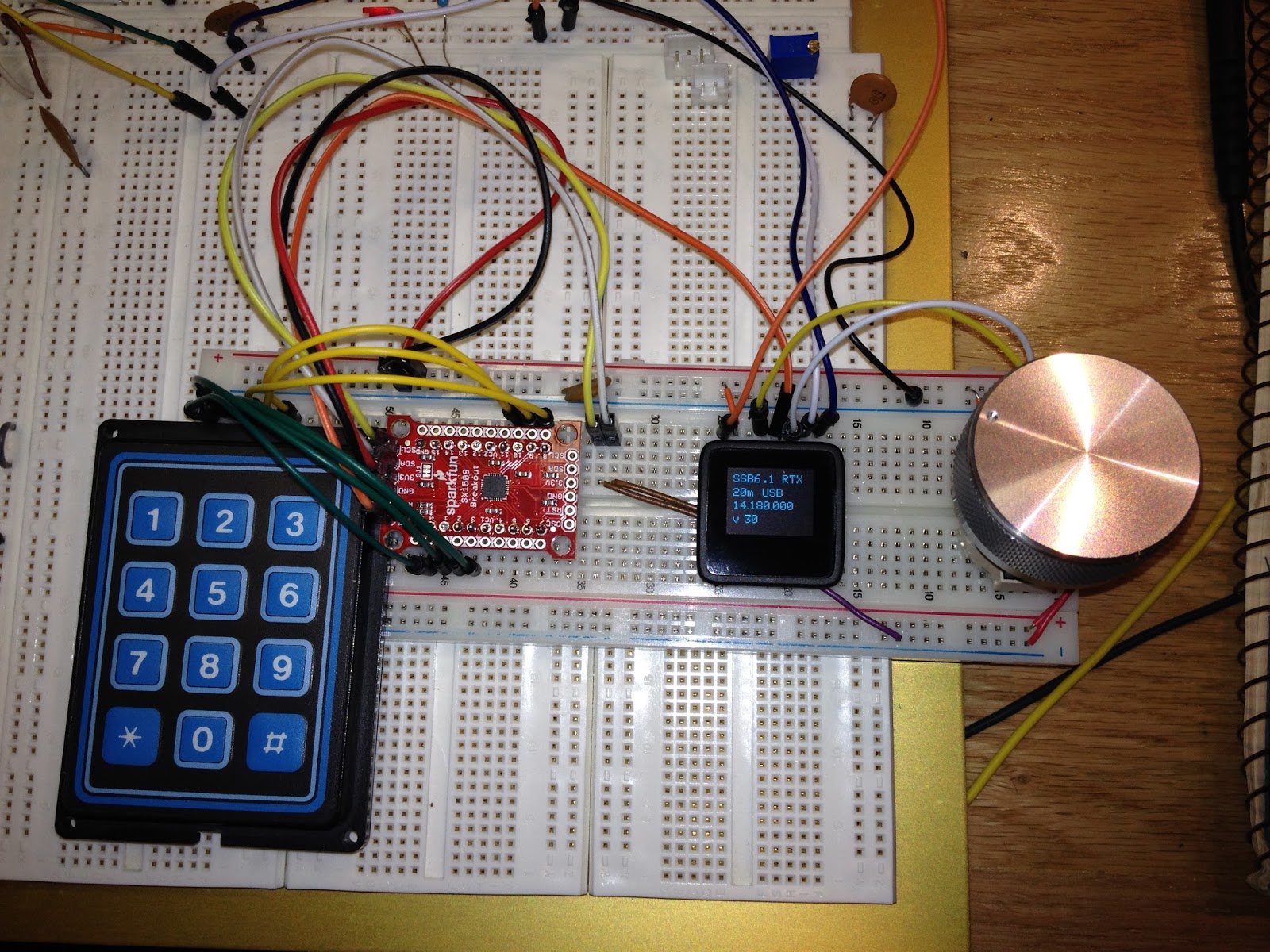
The major update for today was to use the SX1509 I/O expander with a 3x4 keypad.  Lessons learned included wiring the thing up correctly!  I was stumped for a while when the SX1509 stopped working which turned out to be due to the I2C pins being one pin off on the breadboard.  Close is not good enough!  ;-)

Control and UI boards
I wired up the volume and bandwidth digital pots and added support for updates from the UI board.  Of course I had an issue where my volume updates seem to work but the value was not retained by the control Arduino.  It turns out I needed to use the volatile keyword on a boolean flag used to indicate the end of a data packet (always use volatile for variables that are shared with an interrupt routine!).

I am now able to quickly change bands/modes and use the optical encoder to set the frequency, volume, and rx bandwidth.

So, what's next?
  • Decide how to add 17 meters by using the 80m filter slot.
  • Try the transmitter!
  • Add a tx amplifier  (20 to 40 watts would be nice)
  • Add tx post amp filters
  • Add a T/R relay
Stay tuned!

Saturday, June 11, 2016

A Knob!

Man, a knob really makes a big difference in usability!  I found this aluminum knob on Amazon of all places.

I have been wanting to replace the analog poteniometers with digital pots.  I picked up a few from Sparkfun (Microchip MCP4131).  They are very easy to get working; just throw them on the SPI bus with a chip select and give it 16 bits to set the pot value.  These chips only support 7 bit values (only 127 different values) but that may be good enough (they're definitely good enough to get started).

Since I am now throwing a bunch of chips on the SPI bus, I am running out of pins to use as data and chip selects.  Enter the 74hc595 shift register!  I decided to use two of these to extend my outputs.  One is used as the band and mode selection; the band selection uses the lower three bits (fed into the 3-8 decoder) with two other bits to select the mode (only USB or LSB).  This leaves a few more pins for other modes or other future expansion.   The other '595 is being used as the peripheral chip selects; currently only selecting the digital pots.   The great thing is that I used the built in SPI pins and library to drive the chips -- very cool!

A knob on the UI and digital poteniometers and bus drivers
Now I just have to write code that allows the UI to set the digital pot values -- they are currently hard coded and are set at startup.

Tuesday, May 17, 2016

Rearange

I'm right handed so I rearanged the radio and interface boards around to make it more comfortable to play with.  Now I really need a knob 'cause spinning the encoder shaft is tedious...

No button debouncing was terrible so I whipped up a basic timer comparison test and now band selecting actually works.


Right above the Si5351 board from Adafruit are two potentiometers currently wired to the SSB6.1 labeled as WB/BW and WP/PW on the schematic.  I believe WB/BW is for the receiver band width control and adjusting it does seem to change the audio response.  I think the WP/PW pot controls the mic gain.  Above the two pots are three digital potentiometers I got from SparkFun I want to use instead of the analog pots.  I'd like to be able to use the remote UI to control the radio volume, rx band width, and mic gain and digital pots should do the trick.

Saturday, May 14, 2016

SSB6.1 tranceiver with separate UI

I worked on getting a minimalist user interface working with the microView, a optical encoder, and a single button.  The button cycles through the 6 bands.  I did not add any debouncing code so each button press can result in one or several band changes; it makes selecting the band a bit challenging.  I'll work on integrating the SX1509 I/O expander during the next build.

The minimal user interface is on its own breadboard
The microView interacts with the Arduino pro mini via the TTL serial port.  The band button causes the uView to send commands to set the band and frequency while turning the encoder sends delta frequency commands.  On the display I show the band, the frequency the UI thinks is correct, and the frequency the DDS actually is generating.  So far the 2 controllers seem to keep in sync but I did incorporate a syncing mechanism to make sure they are.

Sunday, May 1, 2016

SSB6.1 RTX with band switching

I made some progress with the SSB6.1 radio.  I wound and added the two 40 meter coils and two of the plastic connectors.  I decided it would be easier to use Female-Male jumpers instead of continuing to tack-solder Male-Male jumpers to the PCB.  It turns out that my tack-soldering was a bit more substantial than I had hoped -- one connection required a lot of solder wick to clean and I manged to lift the PCB foil.  Oops!  Well, stuff happens...  I wired up a small jumper on the bottom of the connector and I'll run it directly to the opto-isolator input pin...

I decided to split the radio control from the user interface.  The radio control will use an Arduino Pro Mini while the user interface can vary as desired.  The connection between the two will be via a TTL serial port possibly using RS-485.  This will allow me to have a sealed RF deck and have a remote user interface.

The SSB6.1 has 6 input pins used to select the band.  I wired up a 74hc295 (a 3 to 8 demultiplexor / decoder) to control the band selection.  This chip has 3 digital inputs (binary 0 to 7) and will assert 1 of 8 outputs.  In this application, this will allow only one band to be active at a time.  Fortunately I had a couple in my parts bin (any guesses as to how long?).  It's been sitting in the package for a while but it still works!

There are 4 other inputs to the SSB6.1.  Two are used to select the sideband and two are used to allow SSB or CW transmit keying.  One is labeled as 'CW' and the other is mysteriously labeled 'DT' (on the schematic, this is the DDSPTT input for SSB keying).  I am currently using a couple of digital output pins on the Arduino to select either upper or lower sideband. It's simple and I have a few pins on the Arduino.

On a whim, I threw some $$ at a kickstarter campaign for a fun speech chip that I may use to provide voice feedback.   There is even a version of the chip with words centered around communications (like phonetics).  It should be interesting to play with.

From top left clockwise:  the voice chip, the Arduino Pro Mini with the 74hc295 below it, the SSB6.1, the Si5351 DDS, and finally my trusty old Radio Shack digital logic probe.

With the band and mode selection and a serial connection to the PC in place, I can set the frequency, the band filter, and the mode via keyboard commands.  And, 40 meters sounds great!  :-)


Sunday, April 17, 2016

Old and new parts


I have been building my parts drawer for a few years.  Most of it has come from junque piles at hamfests.  Who can resist looking through boxes of old parts and finding a few gems?  I have built up a stash of keypads of various sizes and types that have been waiting for me to come up with a project.

One issue with the keypads is that you need a way to scan them to recognize the key presses.  Keypads that are wired in a row/column matrix use fewer I/O lines than those that simply close a switch to a common line.  My Grayhill keypads are the latter type; my 16 button keypad has 17 pins -- one for each key and the common pin.  And I have a 20 button keypad that has 21 pins...  I'd like to use a Grayhill keypad with my radio project but 16 pins would tie up all the I/O pins on any reasonably sized microcontroller (not to mention 20 pins).

I like these Grayhill keypads as they allow one to set the label for all keys.  The plastic top of each key pops off and an insert can be placed which will let me to design any layout I want.

I came across the SX1509 I/O expander from SparkFun and ordered a couple.  It provides an I2C interface to 16 I/O pins that can be used in various ways.  Up to 4 devices can be used to provide more I/O pins by setting the I2C address.  Matrix keypads are supported as well as many output options including some cool LED features.

Within a couple of hours of unpacking them, I had a keypad interfaced with the MicroView.

From upper left clockwise:  MicroView, Si5351 DDS, optical encoder, SX1509, Grayhill keypad, SSB6.1
I wired a couple of keys to handle band up and down and updated the firmware to rotate through the DDS frequencies.  Next I have to wire up control lines to the SSB6.1 to actually switch the band pass filters.  Then maybe I'll deal with direct keypad entry of frequencies...

Sunday, March 27, 2016

SSB6.1 with Si5351 RX Working


After a few trials, it looks like I figured out how to get the SSB6.1 to hear stuff.  I had several issues:
  • The board and parts layout diagram had an area for R15-R18 and a part labeled WI (WJ?) but the schematic did not have any reference to these parts.  (Edit:  I discovered that this part is actually M1 -- the letters are transposed on the board so it looks like WI/J.)
  • I was missing the 2 100 Ohm resistors (R42 and R63).
  • C22 is incorrectly labeled as a 2.2uF where a 10uF should be used.
Other than these pretty minor issues, the assembly was straight-forward.  I substituted a couple of non-surface mount resistors for R42 & R63 (they look kinda funny but it will do for now).  The M1 part seems to be for a preamp that actually was included with the parts but I bypassed it since I did not find it on the schematic.  Close examination of a picture of the board from the internet shows a 10pF capacitor installed across 2 pins of M1 instead (the resistors were not populated).

The Si5351 cobbled to the SSB6.1
I decided to only wind the coils for 10m, 15m, and 20m to confirm that I could get something working (and frankly I wanted to get something ready for testing as fast as possible).  I'll wind the 40m coils next.  I am not sure if I'll bother with the 75/80m coils as I'm not sure I will use this radio for that band.  I'd really like to figure out how to get this working on 17m as that is a great band.

The SSB6.1 has an intermediate frequency (IF) of 8 MHz.  During my first tests with the Si5351, I used a DDS mixing frequency of 22 MHz thinking that would give me 14 MHz after the mixer.  Well, it did but I was not able to demodulate signals properly.  The signals all sounded like they were using the wrong side band.  I then tried a DDS frequency of 6 MHz and I started hearing properly demodulated signals!  I then tried a DDS frequency of 13 MHz and was able to hear 15m signals.

After fooling around with the optical encoder code, I am easily able to tune up and down the band.  I display both the DDS frequency and the actual frequency on the microView. I do not have an easy way to switch bands yet; I have to recompile the code and switch jumper connectors.

I read another site about using the Si5351 with a '602 mixer and how the 5351 can overload the '602. I implemented a 10dB attenuator using a few resistors based on information from radio-electronics.com.

Another cool thing about the Si5351 is that I was able to product a sweep frequency to test the receiver incredibly easily.  I simply enabled one of the other clock outputs and it worked great.


Wednesday, March 16, 2016

SSB6.1 RTX

I like portable radios.  I assembled a Wilderness Radio Sierra and an Elecraft K2 and have taken them camping.  They're great for Field Day, too.  But I've been thinking about a backpacking SSB radio that covers several bands that would be fun for day hikes.  Maybe even using it bicycle mobile!

Sometimes you find interesting things on EBay.  I stumbled onto a 6 band transceiver kit (SSB6.1) from a seller in China.  I found it intriguing so I dropped the sixty bucks to have a building adventure.

(Before anyone gets upset about my not buying something from the US:  I also have kits for the R2 and T2 from Kanga US that I am slowly working on.)

This shows the complete contents of the box:  a bunch of surface mount parts, a few NE602s, a few opto-isolators, coil forms, and some connectors.  No instructions, no parts list, no schematic.  Fortunately, the schematic and parts layout are available on the InterWeb.

Soldering surface mount parts can be a challenge but a fine tip iron made that straight-forward.  I was really concerned about winding the coils.  I've wound plenty of toroidal coils but never these.  It turns out (yeah, I said it) that they were pretty easy to wind - I just had to pay attention to what I was doing.

It only has an exciter output level of about 20 mW so I'll need to investigate some amplifier options.

Si5351

Adafruit has a board for the Si5351A.  For 8 bucks you get a itty bity board with 3 clock outputs with a range of 8 KHz to 150 MHz.  I picked up a few to play with homebrew HF radios.  (EtherKit has a version, too.)

I am using the EtherKit library for Arduino.  It is very straight-forward and I was generating clock signals in no time.

This shows the Arduino MicroView handling a rotary encoder and the I2C to the Si5351.


Tuesday, January 6, 2015

Icom AH-4 Remote Tuner

My current antenna is the B.A.L. -- a large, horizontal loop that's about 150 meters of wire about 15-20 meters up in the trees around the yard.  I think it's a great all band antenna.

I buried a couple of coax runs from the shack wall to a spot about 15m away behind a large bush.  The ladder line from the loop falls down to this spot so I do not have wires directly hanging off the house (which makes the YL happy).  I was using a DX Engineering MAXI-CORE Balun and was happy with the results.  (As an aside:  I love hamfests!  I picked up this used balun for a song.)  I used this setup for a few years and have been pretty happy with the results. 

Since the loop is a non-resonant antenna, the SWR can be high.  I've been using the tuners built into my transceivers (Elecraft K2 & K3) but have been concerned about loss in the coax.  Since I only run 100 watts or less, I want every bit of power to get to the antenna and not be used to heat the coax. Placing a tuner at the end of the coax run is supposed to reduce the coax loss.  I had always planned on adding a remote tuner when the budget allowed.  When I buried the coax, I also threw in a couple of runs of CAT-5 cable that I had laying around for use for some sort of remote control.


The remote connection at the end of the coax run
I recently acquired an Icom AH-4 remote antenna tuner.  I am using one of the CAT-5 runs as the control cable for the AH-4; I simply used each twisted pair together for the power and control signals.  I no longer use the balun.


All connected and ready to go!
Since I am using this tuner with a non-Icom radio, I needed a way to tell the tuner to initiate the tune cycle.  I whipped up the circuit described as the universal controller and it seems to do the job. (Edit Jan 2019: The link to the universal controller diagram http://www.k2.dion.ne.jp/%7Esradio/AH-4En.htm no longer works!  There is a discussion on eham with a diagram that I think is similar.)  I do plan on building a better controller that will initiate the tune cycle and then key the radio automatically.

The 'controller' in the shack
I've been very happy with the tuner so far.  It finds a decent match (less then 1.5:1) on all bands and I believe it has made a difference.  I don't have empirical evidence to support that, though!  At least I no longer worry about loss in the coax...

Saturday, December 20, 2014

Fun with SLO2016 LED displays

I love going to hamfests; you never know what you will find.  At one 'fest a few years ago, I picked up several SLO2016 LED matrix displays. I had no idea what they were when I bought them -- they just looked kind of cool and I thought they might work for small, minimal displays (as opposed to a larger LCD display). After a quick web search, I found this data sheet.

They are modules of 4 little 5x7 LED matrix characters.  They have 7 data lines for 127 characters, 2 address lines to determine which character is updated, and a enable/write line.  They can be chained together by sharing the data and address lines and controlling the individual enable/write pin on each display.

I posted a video to youtube showing 3 displays chained together for a 12 character scrolling display controlled by an Arduino Pro Mini.  You can find several other videos with examples. 

I got a request for the code for the scrolling text.  I make no claim as to how wonderful my code is; if it is useful, have at it!

The Code

Sunday, September 1, 2013

EEVBlog video on Arduino

This YouTube video captures my feelings about the Arduino boards.  It's from Dave Jones of EEVblog and he makes his, ah, unique comments about the whole project and I found that I agree with most of what he says.

Certainly, there's a ton of Arduino stuff out there on the web, but this video really expressed the essence of why I am using these boards now.